ATLAS
Designed power converters for a tethered multirotor with AUW of 10Kgs
This is my Bachelor of Engineering capstone project undertaken in a group of 3 with Adithya Ramanujam and Chirag Shah. After my internship on Project AURUS, Drishti Works decided to fund us for working on ATLAS.
The ATLAS project was started at Drishti Works to develop a high payload tethered multirotor with a primary goal: “To build a tethered UAV which will have all the features needed to serve as a large base platform upon which further expansions/ accessories can be added to serve various use cases, and with enough payload capacity to carry mini-drones, sensors, cameras, life saving attachments, etc.”
But the basic prototype put together by the Drishti back in December-January 2018, was a failure because of several design flaws. So we had to revive the project and develop a better system which can be the stepping stone to a fully functional tethered multirotor.
In a tethered multirotor system, you cannot directly transmit the power at the working voltage of the multirotor. Suppose the multirotor motors run at 12V(3S) with each of them drawing 15A of current, you will have current peaks of about 25A at maximum throttle. In such an octocopter system, the total power draw goes to 1500W to 2500W, with the total current draw of up to 200A. If the multirotor is required to fly at 100 or even 50 meters of altitude, the required cables to transmit that power would be impractically thick and heavy, considering the huge wire losses at such currents. Hence, some form of power conversion is a must.
If 400V DC is used for transmission; to transmit the same 2500W, the current draw would be just about 7A instead of the 200A! That is a significant difference and now the only problem is to make 400V to 32V step-down modules to be mountable on the multirotor, with the main factor being weight.
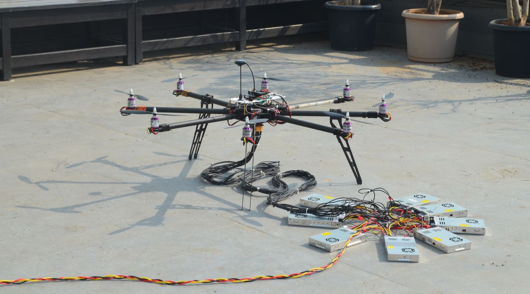
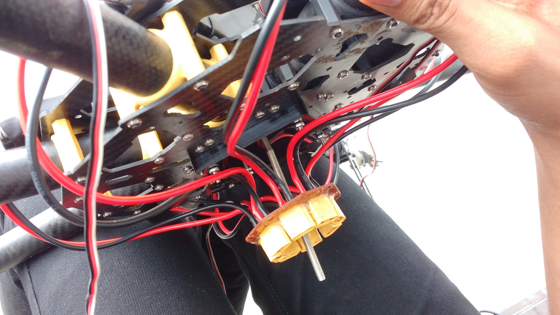
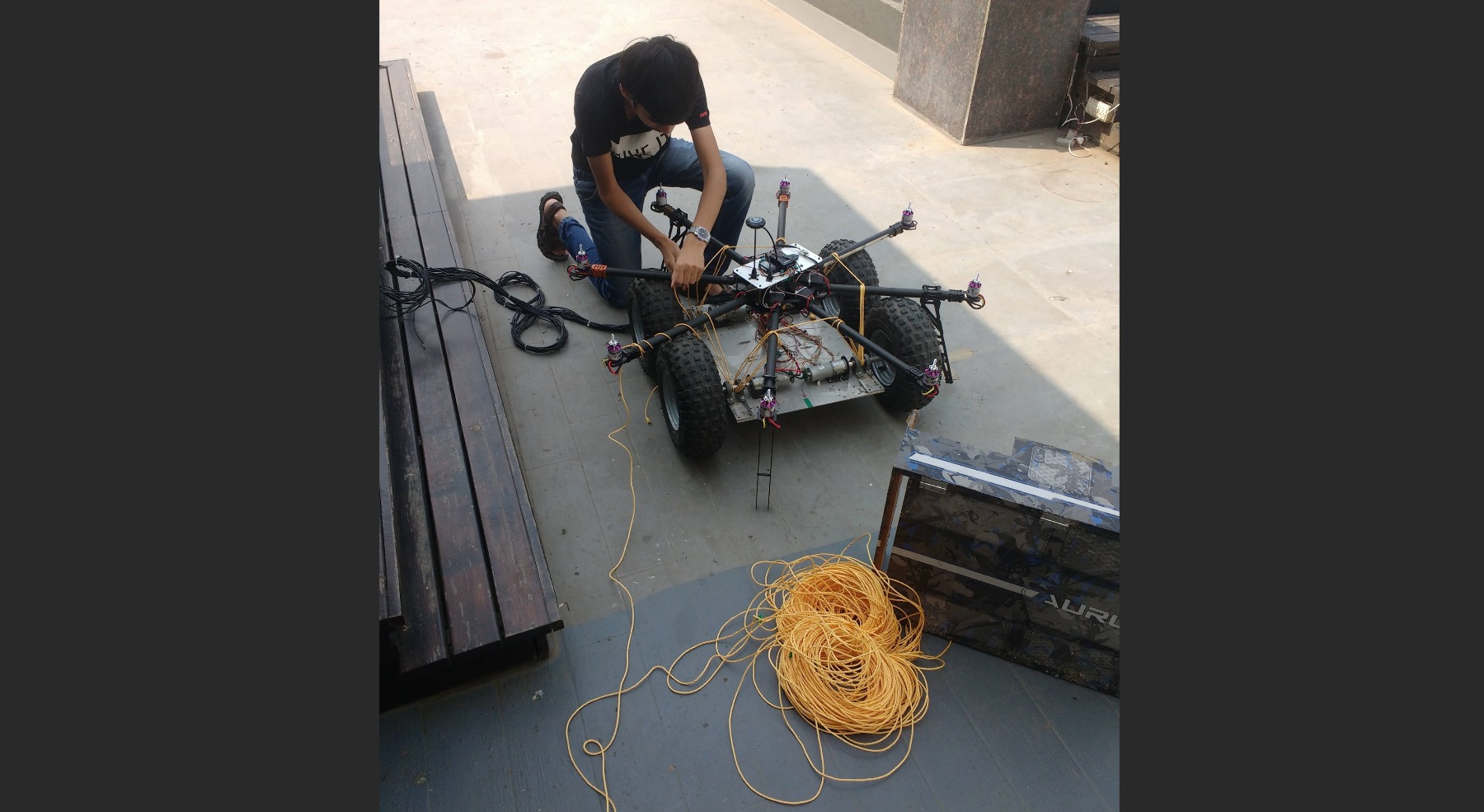
But before all that, it was necessary to have a basic platform to work on. So we decided to build a tethered octocopter, but with direct transmission of the power required by each motor, as the stepping stone. The idea was that once we have a base system ready, we can improve it by adding efficient power transmission and a better tether to increase flight altitude and payload capacity. So this system has 16 wires in the tether with a maximum height of just 12ft, which is a reasonable value for testing out long-duration flight capabilities.
We performed a successful 70min continuous and autonomous flight at the end of semester VII:
The next step was to build the step-down modules for on-board power conversion to be done. This is a really challenging step because of the design of such converters being so very tricky!
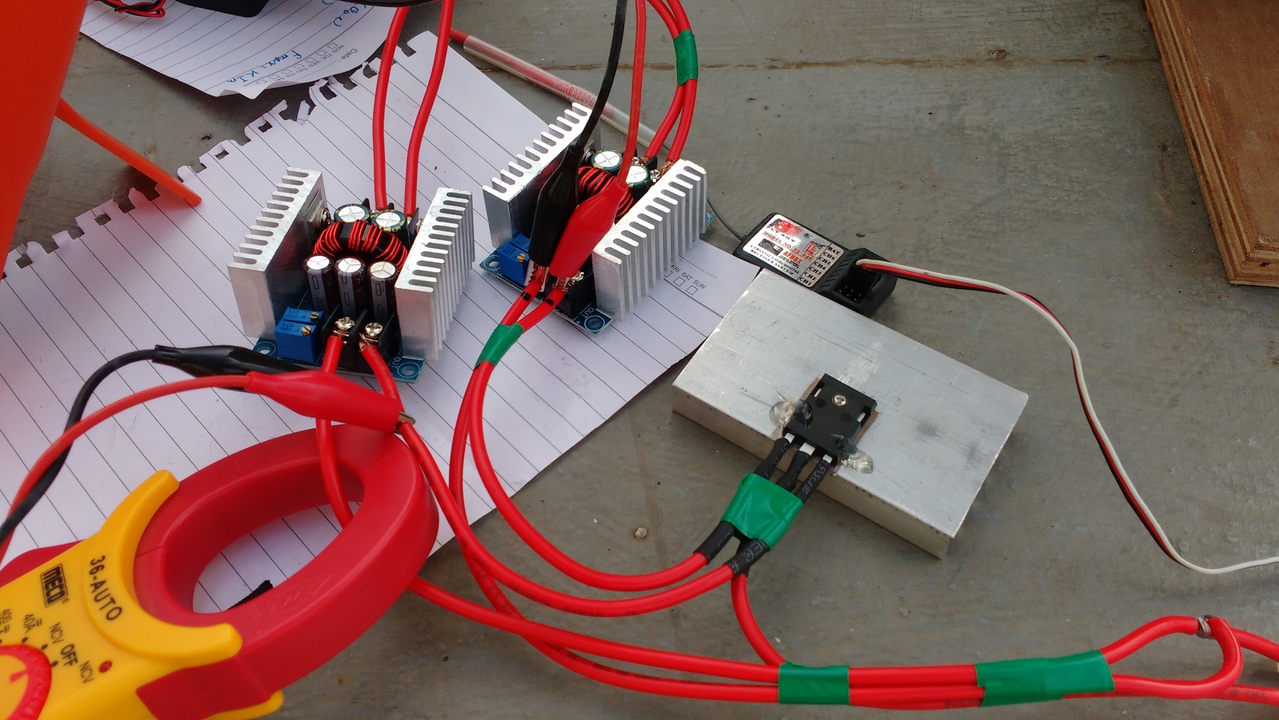
We decided to go with 32V(8S) motors for a better configuration, and accordingly, based on the availability of step down converter ICs, we decided to get the power conversion done in stages - 400V to 140V and 140V to 32V.
The LTC3895 was used as the controller for the 140V to 32V module and designed a PCB for it. All the components shown in the board below were hand soldered, even the tiny QFN-like MOSFETs using hot air reflow, and it was a great experience!
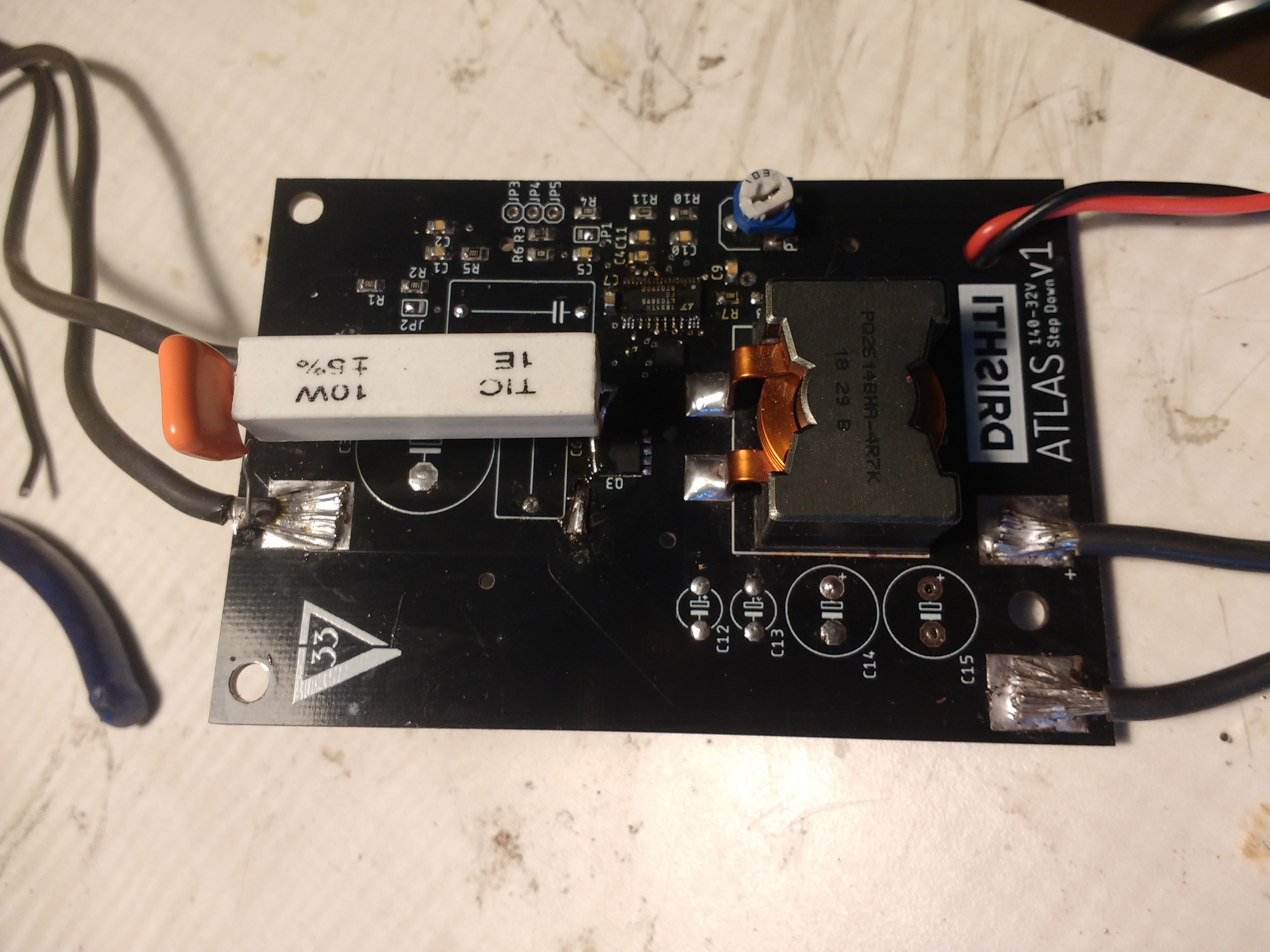

But we faced issues with the designed layout as described in this forum here, and had to design a new set of PCBs (revision 2).
After further optimizing the design, the second revision of the PCB was somewhat of a success and we have the required output. The video of the PCB testing along with its thermal profile can be seen here:
However, design was still not quite successful at higher current loads. We realized at the end that we simply lacked the expertise needed to create such high voltage converters at targeted form-factor limits. Over the course of my work the following year on the high power battery charger, I learnt more about power converters and the mistakes we made. Atleast two more iterations would have been necessary to meet all the required specifications.
We did still learn a lot and graduated as Electronics Engineers! The final project report is available here: http://bit.ly/ATLAS-Report
